To ensure the safety of personnel and equipment during installation, only professional electricians or professionally qualified personnel are allowed to transport and install this product.
1. Installation environment confirmation
In order to ensure the normal and safe operation of the equipment, please make sure that your site meets the following requirements:
The equipment is required to be setup on the floor with flame-proof material, and the flooring is constructed with the U-bar. The floor is required to be flat and firm enough to support the weight of the equipment;
Adequate ventilation and no direct sunlight;
Temperature:-10°C~40°C, no rapid temperature change;
Humidity: ≤70% RH(No steam condensation);
Altitude: <2000;
No high-density dust, no flammable or corrosive components around the equipment.
Attention:
1. When installing the equipment, care must be taken to maintain proper clearance from fixed objects (e.g. walls) and neighboring cabinets to ensure ventilation and safe escape in the event of danger, and at least one person should be left with space ≥ 600 mm to pass around the equipment;
2. The top of the equipment must leave some space for ventilation, operation and maintenance, usually not less than 500 mm.
Warning:
When moving the unit, use a forklift truck that meets the rated lifting capacity and has the proper fork span. The cabinet must be lifted from the bottom. Support the cabinet from all four sides when lifting and take precautions to prevent the cabinet from tilting during transportation.
2. Electrical connection of the equipment
Requirement for cable:
All the cables required a sufficient current-carrying capability. The current-carrying capability will be affected by the environmental conditions, insulating materials, method of laying, materials of wire, and cross sectional area;
All the cables must based on the maximum AC current and reserve some retained Current;
All the cables on the same side must have the same parameters and form;
The cable must be flame-proofed.
The cable selection calculation formula is as follows:
1. Formula: Current = Power / Supply Voltage.
2. For this equipment, the power per channel is 60V * 50A = 3000W.
3. CE-6012n-60V50A: The equipment has a total of 12 channels, with a total power of 3000W * 12 = 36000W.
4. Therefore, the total current demand is 36000W / 380V ≈ 94.74A.
Cables can be selected by looking up the AWG vs. current carrying capacity comparison table.
Requirement of power supply:
The power supply must meet the below conditions:
AC Voltage: 380 V±15% , three-phase four-wire + Protective ground wire.
Frequency: 50/60Hz ±5Hz.
PGND cable resistance should be less than 4, and a TN-S power supply or TT power supply is required.
Users are required to set up the air switch or power switch with related capacity, and these switches must independently operate for this equipment.
3. Wiring instructions
Before connecting the power, please disconnect the power to ensure the safety of the connection process.
Only professional electricians or personnel with professional qualifications are allowed to perform the following operations!
Connect the one-to-five power cable to the device end, from left to right they are Phase A, Phase B, Phase C, Neutral line (N line), and the Protective Earth line, also known as the Ground line or PE line.

Before connecting the power cord to the power supply side, turn off the air switch on the power supply side to disconnect the power.

Connect the three-phase power of the one-tow-five power cord to the power distribution cabinet in color sequence, and connect the zero and ground wires at the same time.
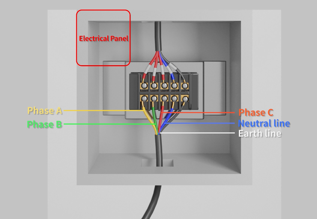
The power supply side should be: 380 V alternating current.
The power distribution cabinet is only for demonstration, please refer to the actual situation.
Then use the network cable to connect the device to the switch, and then use the network cable to connect the switch to the computer.
Finally connect the battery. Connect one end of the voltage and current wires to the voltage and current collection port respectively, and the other end to the battery.

Connect the voltage and current wires to the same lugs on the battery, be sure to identify the positive and negative lugs before connecting.
Thick black line is negative current sampling line, thick red line is positive current sampling line. The thin black line is the negative voltage sampling line, and the thin red line is the positive current sampling line.

Note: When connecting the battery, the coil on that end of the device must be tightened without wobbling, otherwise the long test time will cause the current terminals to warm up and turn red, affecting the service life of the device.
3. Equipment startup
After completing the wiring of the equipment, close the gate to energize and toggle the red main power switch at the bottom of the back of the equipment.
If the equipment does not start after the switch fluctuates (the touch screen does not light up), check whether the emergency stop switch on the front of the equipment has not been reset.
Turn the button clockwise to reset, then toggle the switch back up.

The screen lights up to indicate that the device is successfully powered on, and you can then perform a series of operations on the screen

Part 2: Introduction to the touch screen
This interface is a menu selection function, in which you can choose to enter the interface of operation data, fault record, parameter setting, auto-calibration, overview, setup, and switch-on/off.
The top right of the interface displays the current time and communication connection status.


Enter the operating data page, you can view the battery voltage, current, power and other parameters.

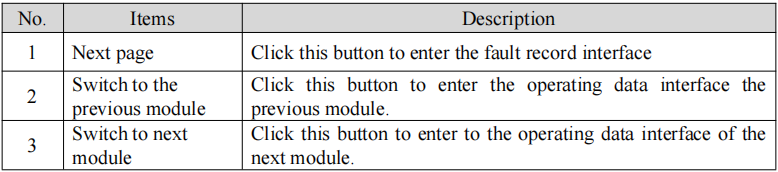
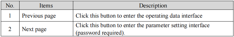
Fault interface press the previous page to enter the parameter operation data page, press the next page to enter the parameter setting page (need to enter the password).

Auto-calibration page to be used with auto-calibration tooling.

After the system initialization is completed, it enters the overview page, where you can view the operating status, voltage values and current values of all physical channels.


Note: Physical channel information is shown here, please check the client software for actual channel information.
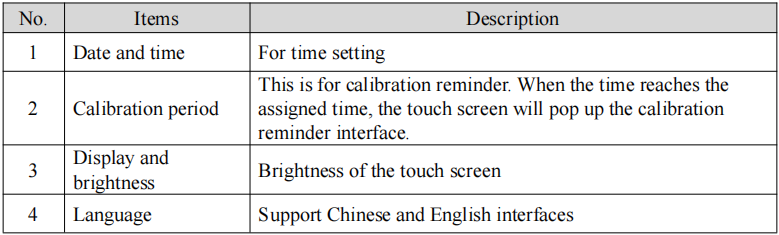
This screen is the setup screen, where you can set the date and time, calibration period, language, and so on.

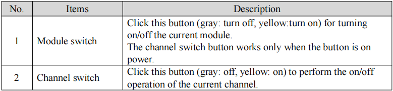
5. Equipment switching
Switching interface can select module switching and channel switching.

Part 3: Software installation
Part 4: Introduction to basic software functions
After completing the above steps, you can begin your testing in BTS8.0 software!


